High Energy Piping Walkdowns
20 Nov 2020
Discussing the ASME B31.1 Power Piping Code, Chapter VII Operation and Maintenance - Covered Piping System Walkdowns
Since the occurrence of catastrophic high energy steam line failures in the mid 1980's, the electric utility industry has focused on the asset integrity management (AIM) of high energy piping (HEP) systems. The HEP walkdowns and stress analysis Intertek AIM performs are required per American Society of Mechanical Engineers (ASME) B31.1 Power Piping Code, and are deemed necessary to ensure safe facility operations and the reliability of generating units based on the provisions of this code. The importance of HEP system walkdowns in identifying malfunctioning supports can be seen in the table of Initial Hot Walkdown Surveys of Spring Supports (Table 1).
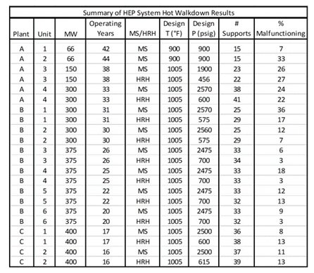
Table 1. Initial Hot Walkdown Surveys of Spring Supports
ASME B31.1/Chapter VII – states that a program should be established to provide for the assessment and documentation of the condition of all covered piping systems (CPS). As a minimum for electric power generating stations, the CPS are to include Nominal Pipe Size (NPS) 4-inch and larger of the main steam, hot reheat steam, cold reheat steam, and boiler feedwater piping systems. Condition assessment documentation should contain pipe support hot and cold walkdown readings and conditions since the last condition assessment for piping systems that are operated within the creep regime.
Intertek AIM HEP walkdown procedure PF-13 follows the ASME B31.1 Guidelines. Hot and cold walkdown record forms, recommended in the ASME B31.1 Nonmandatory Appendix V (Recommended Practice for Operation, Maintenance, and Modification of Power Piping Systems), are used to document the status of the system supports and to record spring hanger readings. Isometric drawings, with identification of all supports, are used to document pipe low points, possible piping interferences, lagging and insulation damage, and any other significant anomalies/discrepancies. Trams (movement indicators), are established at select locations to measure the piping thermal displacements. Documentation includes photographs of all piping system supports and piping system anomalies.
ASME B31.1 Chapter VII requires piping systems integrity evaluations of the effects of malfunctioning supports, and unexpected piping position changes, which are defined as significant displacement variations from either the as-designed or as-built piping analysis.
Malfunctioning supports affect the stresses in the HEP system, which can lead to piping failures, as shown in this table of Girth Weld In-Service Creep Cracks discovered at 15 plants between 1998 and 2018 (Table 2).
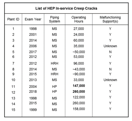
Table 2. Girth Weld In-service Creep Cracks (Gr P11, P22 and P91 Piping Systems)
As part of an Intertek AIM piping system evaluation, an as-designed mathematical model is prepared based on the design specifications, including the designed support travel. The as-designed piping stress analysis results include two analyses: sustained load (SL) and the thermal expansion stress range (SE), which are compared to the code of record allowable stress values.
Intertek AIM then performs a simulation as-found piping stress analysis. This as-found piping stress analysis is a modification of the as-designed piping stress analysis, which considers the applicable spring hanger and interference anomalies.
Figure 3 is a comparison of the observed piping displacements to the initial as-designed piping displacements and to the simulation as-found piping displacements. This piping system profile diagram methodology is used to reveal and evaluate significant piping displacement anomalies.
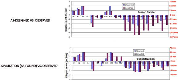
Figure 3. As-designed vs. As-found Piping Stress Analysis Piping Displacement Profiles
Figure 4 shows an example of sustained load (a combination of dead weight, pressure, and external loads) stress contours, comparing the as-designed to the simulation as-found piping stress analyses. It illustrates that the current behavior of the piping system may have high-stress locations that were predicted as low stress in the as-designed piping stress analysis. Furthermore, the high-stress location in the as-designed piping stress analysis may actually have very little creep damage and the reexamination intervals can be increased.
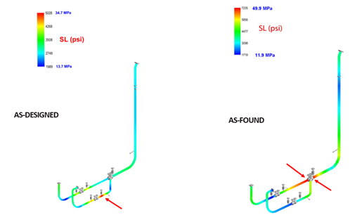
Figure 4 As-designed vs. As-found Piping Stress Analysis Stress Contours
Intertek AIM is a recognized industry leader in ASME B31.1/Chapter VII HEP walkdowns and stress analysis. For over twenty years our qualified engineers and technicians have performed hundreds of HEP walkdowns and stress analyses, as well as nondestructive examinations, remaining useful life evaluations, fitness for service assessments, failure analyses, and asset integrity management program development at power plants worldwide.

Robert Gialdini,
Sr. Mechanical Engineer
Mr. Gialdini is a registered Professional Engineer (Mechanical) with experience that includes analysis of steady-state and transient stress, strain, and temperature fields using Ansys finite element software. His experience also includes fatigue and fracture analysis of mechanical components, high energy piping condition assessment and life management evaluations using CAEPIPE and CAESAR II piping software, and code compliance verification for pressure vessels per ASME Boiler Codes.