SUN - UL 924, Emergency Lighting and Power Equipment
Effective March 11, 2016
Effective Date (see Schedule below): April 29, 2016
Impact Statement: A review of all Listing Reports is necessary to determine which products comply with new/revised requirements and which products will require re-evaluation. NOTE: Effective immediately, this revised standard will be exclusively used for evaluation of new products unless the Applicant requests in writing that current requirements be used along with their understanding that their listings will be withdrawn on Effective Date noted above, unless the product is found to comply with new/revised requirements.
Overview of Changes: (Specific details of new/revised requirements are found in table below):
- Updated battery requirements to reflect developments in battery technology and standards
- Derangement signals should change status when identified triggers occur
- Self-testing / self-diagnostic equipment revision to align with NFPA 101
- Revised requirements for graphical symbol exit signs
- Exit sign marking to indicate rated (rather than maximum) viewing distance
- Marking for photoluminescent signs
- Maximum mounting height marking for emergency luminaires
- August 27, 2015 = 8 Month Report Review – Intertek will review all Reports. Update if compliance is verified or issue Findings Letter/Quote for any re-evaluations needed
- October 29, 2015 = 6 Month Quote Cut-off – Quotes returned for necessary re-evaluations
- March 28, 2016 = 30 Day Warning – Client advised of all non-compliant Reports to be Suspended
- April 29, 2016 = Effective Date – ATM Suspended for all non-compliant Reports
Client Action Required:
Information - To assist our Engineer with review of your Listing Reports, please submit technical information in response to the new/revised paragraphs noted in the attached or explain why these new/revised requirements do not apply to your product (s).
Current Listings Not Active? – Please immediately identify any current Listing Reports or products that are no longer active and should be removed from our records. We will do this at no charge as long as Intertek is notified in writing prior to the review of your reports.
| Clause | Verdict | Comment | ||||||||||||||||||||||||||||
|---|---|---|---|---|---|---|---|---|---|---|---|---|---|---|---|---|---|---|---|---|---|---|---|---|---|---|---|---|---|---|
| 22 | Info | Batteries Updated battery requirements to reflect developments in battery technology and standards | ||||||||||||||||||||||||||||
| 22.1 | Info | Deletions are shown A battery provided as part of any assembly shall have a rating and capacity such as to comply with 46.1. Exception: This requirement does not apply to an auxiliary equipment battery. | ||||||||||||||||||||||||||||
| 22.1.1 | New clause added; A battery shall be of the rechargeable (secondary) type and shall comply with the Short Circuit, Abnormal Charging, and Forced-Discharge Tests of the Standard for Household and Commercial Batteries, UL 2054. Exception: Lithium ion batteries shall comply with the same tests of the Standard for Lithium Batteries, UL 1642. | |||||||||||||||||||||||||||||
| 22.2 | Additions to existing requirements are underlined and deletions are shown Unless marked or specified otherwise by the manufacturer, the rated battery voltage is to be calculated on the following basis:
| |||||||||||||||||||||||||||||
| 22.3 | Additions to existing requirements are underlined and deletions are shown | |||||||||||||||||||||||||||||
| 22.5 | Additions to existing requirements are underlined and deletions are shown
| |||||||||||||||||||||||||||||
| 28 | Info | Derangement Signals Derangement signals should change status when identified triggers occur | ||||||||||||||||||||||||||||
| 28.1 | Additions to existing requirements are underlined and deletions are shown Equipment incorporating a) Disconnection Exception: Disconnection of the battery need not be considered for equipment with batteries not intended for replacement, maintenance or service, such as an emergency battery pack or equipment marked in accordance with 70.1.13. b) The battery is actively supplying a remote (but not concurrently a local) load; c) The battery charger is not receiving its intended charging voltage; or d) For self-testing / self-diagnostic equipment, detection of a non-functional feature during a self-testing/self-diagnostic routine, in accordance with 30.1. Compliance shall be determined by the Normal Operation Test, Section 45. | |||||||||||||||||||||||||||||
| 30 | Info | Self-Testing/Self-Diagnostic Equipment Self-testing / self-diagnostic equipment revision to align with NFPA 101 | ||||||||||||||||||||||||||||
| 30.1 | Additions to existing requirements are underlined and deletions are shown Equipment that contains self-testing/self-diagnostic capability shall automatically perform a a) Automatic load transfer system functionality; b) Battery charger system functionality; c) Battery terminal voltage no less than 87.5 percent of nominal; and d) Availability and functionality of connected loads. Based on preset or recalibrated levels indicating load availability, a derangement signal shall occur when the levels deviate by more than 50 percent for exit signs and inverters, and by more than 10 percent for central systems and unit equipment. The means to determine the availability of connected loads shall be appropriate for the equipment technology, such as a measurement of impedance (for incandescent loads) or drive current (for LED loads). The equipment shall be tested in accordance with 45.4 and 45.5. | |||||||||||||||||||||||||||||
| 40B | Info | New section added establishes construction requirements for graphical symbol exit signs; Graphical Symbol Exit Signs – Construction | ||||||||||||||||||||||||||||
| 40B.1 | A graphical symbol exit sign shall include the running man symbol and arrow, such as shown in Figure 40B.1. The arrow shall be located on the side of the sign toward which the running man is facing (i.e., for a running man facing towards the right, the arrow shall be to the right of the running man). Exception: A second arrow is permitted on the opposite side of the running man, pointing in the opposite direction. | |||||||||||||||||||||||||||||
| Figure 40B.1 | Info | Running man symbol and arrow  | ||||||||||||||||||||||||||||
| 40B.2 | The arrow shall be oriented up, down, horizontally pointing away from the running man, or 45 degrees from horizontal pointing away-and-up or away-and-down from the running man. | |||||||||||||||||||||||||||||
| 40B.3 | Additional text or symbols that provide supplemental evacuation information (such as a wheelchair symbol, indicating an accessible means of egress) is permitted on the side of the sign opposite to that of the arrow. No content that detracts from the visibility of either the arrow or the running man symbol is permitted. | |||||||||||||||||||||||||||||
| 40B.4 | Figures 40B.2 and 40B.3 specify minimum dimensions for specific elements of the running man and arrow based on a minimum required sign height of 6 inches (152 mm). All other elements shall retain proportionality to the elements whose dimensions are specified. For larger signs, all dimensions shall be increased proportionately. | |||||||||||||||||||||||||||||
| Figure 40B.2 | Minimum dimensions for specific elements of the running man 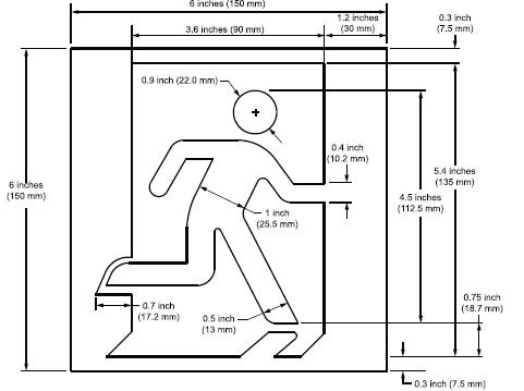 | |||||||||||||||||||||||||||||
| Figure 40B.3 | Minimum dimensions for specific elements of the arrow 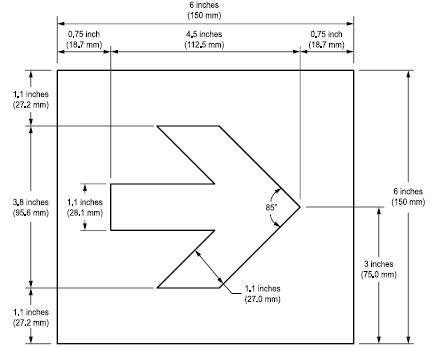 | |||||||||||||||||||||||||||||
| 40B.5 | The contrasting color space between the arrow and the inside of the running man symbol door frame shall be no less than 1 inch (25.4 mm) measured at the closest point. | |||||||||||||||||||||||||||||
| 40B.6 | The brightness (luminance) of the background space between the running man and the door frame shall be comparable to that of the arrow, as determined by the Luminance Measurement Test of Section 41.3. | |||||||||||||||||||||||||||||
| 42 | Info | Markings Exit sign marking to indicate rated (rather than maximum) viewing distance | ||||||||||||||||||||||||||||
| 42.8 | Additions to existing requirements are underlined and deletions are shown Exit signs subjected to the Observation Visibility Test, Section 41.2, at a viewing distance of less than 100 feet shall be marked with the following or an equivalent statement: ²Notice – | |||||||||||||||||||||||||||||
| 4.15.1, 4.15.2, 4.15.3, 4.27, 31.5, 50.3, 70.1.7, 73.2, SD2.4.2, SB (numerous clauses) | Replaces the term “inverter/charger pack” with “emergency ballast”, adds the term “emergency driver”, and adds the term “emergency battery pack” where appropriate to refer to either technology throughout Supplement SB. New SB5.8 requires emergency battery packs evaluated for compliance with the lumen output requirements (SH3.3) to be marked with the maximum mounting height of the connected luminaire, per SH4.2. Note that SH4.2 allows this information to be included in the installation instructions. Will require review of the installation instructions (or product markings) for previously certified emergency battery packs for compliance with the marking requirement of SB5.8. This will involve a calculation, per SH4.2, based on previously acquired data; no additional testing is anticipated. | |||||||||||||||||||||||||||||
| SUPPLEMENT SG | Info | PHOTOLUMINESCENT EXIT SIGNS | ||||||||||||||||||||||||||||
| SG4.2 | Info | Visibility tests | ||||||||||||||||||||||||||||
| Table SG4.1 | Additions to existing requirements are underlined below
| |||||||||||||||||||||||||||||
| SUPPLEMENT SH | MINIMUM LIGHT OUTPUT FOR EMERGENCY LIGHTING EQUIPMENT | |||||||||||||||||||||||||||||
| SH4 | Marking | |||||||||||||||||||||||||||||
| SH4.2 | Changes the permissive mounting height declaration in emergency luminaire installation instructions to a required marking, based on calculations derived from the lumen output testing of SH3.3. Will require review of the installation instructions for emergency luminaires and unit equipment provided with integral batteries as their emergency source. |
CUSTOMERS PLEASE NOTE: This Table and column "Verdict" can be used in determining how your current or future production is or will be in compliance with new/revised requirements.