SUN - UL 756, Coin and Currency Changers and Actuators
Effective December 31, 2015
Effective Date (see Schedule below): December 31, 2015
Impact Statement: A review of all Listing Reports is necessary to determine which products comply with new/revised requirements and which products will require re-evaluation. NOTE: Effective immediately, this revised standard will be exclusively used for evaluation of new products unless the Applicant requests in writing that current requirements be used along with their understanding that their listings will be withdrawn on Effective Date noted above, unless the product is found to comply with new/revised requirements.
Overview of Changes: The changes with respect to the previous edition include the additional requirements for switching devices and overcurrent protection. Specific details of new/revised requirements are found in table below.
Schedule: So that shipping of products with Listing Marks will not be interrupted, an approximate schedule has been established to ensure Listing Reports are found compliant by Effective Date:
- May 30, 2015 = 7-8 Month Report Review – Intertek will review all Reports. Update if compliance is verified or issue Findings Letter/Quote for any re-evaluations needed
- June 30, 2015 = 6 Month Quote Cut-off – Quotes returned for necessary re-evaluations
- November 30, 2015 = 30 Day Warning – Client advised of all non-compliant Reports to be Suspended
- December 31, 2015 = Effective Date – ATM Suspended for all non-compliant Reports
Fees: An initial review of Listing Report (s) will be covered by a direct billing project and will be invoiced at not more than $1000 per report.
Client Action Required:
Information - To assist our Engineer with review of your Listing Reports, please submit technical information in response to the new/revised paragraphs noted in the attached or explain why these new/revised requirements do not apply to your product (s).
Current Listings Not Active? – Please immediately identify any current Listing Reports or products that are no longer active and should be removed from our records. We will do this at no charge as long as Intertek is notified in writing prior to the review of your reports.
| Clause | Verdict | Comment |
|---|---|---|
| 23 | Info | Overcurrent Protection |
| 23.2 | Info | Motors |
| 23.2.2 | Additions to existing requirements are underlined and deletions are shown The protection required by 23.2.1 may be accomplished by one of the following:
a) Protective electronic circuit(s) in accordance with 23.2.3 and 23.2.4 or complying with the Standard for Electronically Protected Motors, UL 1004-7; b) Impedance protection complying with the Standard for Impedance Protected Motors, UL 1004-2; c) Thermal protection complying with the Standard for Thermally Protected Motors, UL 1004-3; or d) Other protection that tests show is equivalent to the protection mentioned in (a) to (d). | |
| 23.2.3 | Deletions are shown A protective electronic circuit providing motor protection in accordance with 23.2.2 a) Standard for Tests for Safety-Related Controls Employing Solid-State Devices, UL 991; or b) Standard for Automatic Electrical Controls for Household and Similar Use, Part 1: General Requirements, UL 60730-1, as well as the specific applicable Part 2. Exception: A motor protected by protective electronic circuits is not required to comply with UL 991 or UL 60730-1 if it does not create any hazard under abnormal conditions with the protective electronic circuit rendered ineffective (open or short-circuited). | |
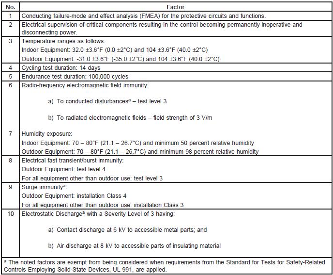
| 23.2.5 | New clause added; With reference to 23.2.3 and 23.2.4, the factors outlined in Table 23.1 shall be considered when evaluating a protective electronic circuit. | |
| Table 23.1 | New table added; Factors to be considered when evaluating protective electronic circuits
| |
| 26 | Info | Switches and Controllers |
| 26.5.1 | New clause added; A switch or other control device shall have a rating not less than that of the load that it controls. Items to consider in determining the device rating include the voltage, current, power factor, control device ambient temperature and other similar parameters. | |
| 26.7.1 | New clause added; A switch or other similar device used to control an inductive load (other than a motor), such as a transformer or an electric-discharge-lamp ballast, shall: a) Be rated for not less than twice the full-load current of the transformer or ballast; or b) Have an inductive rating at least equal to the load it controls. | |
| 26.20 | New clause added; An operating control that complies with 26.15 shall also comply with the following: a) For electronic controls – Installation Class 2 for electromagnetic compatibility (EMC) shall be in accordance with Electromagnetic Compatibility (EMC) – Part 4-5: Testing and Measurement Techniques – Surge Immunity Test, IEC 61000-4-5; b) Category II shall be the overvoltage category; c) Insulating materials shall have a minimum comparative tracking index (CTI) of 100 (Material Group III); d) The applicable pollution degree shall be as specified in 21.3 (a) – (d); and e) The operating control (limiter) endurance cycle requirements shall be as specified in the Standard for Automatic Electrical Controls for Household and Similar Use; Part 2: Particular Requirements for Temperature Sensing Controls, UL 60730-2-9, Table CC.2. | |
| 71A | New section added; Overload and Endurance Test – Switching Devices | |
| 71A.1 | This test applies to switches or other similar control devices as specified in 26.5.1, 26.6, 26.7, 26.7.1 or 26.8. | |
| 71A.2 | A switching device in a coin and currency changer and/or actuator shall perform acceptably when tested as specified in 71A.2 – 71A.8 for overload and endurance. There shall be no electrical or mechanical failure nor undue burning, pitting or welding of contacts, or striking of an arc to dead metal parts. | |
| 71A.3 | The tests on switching devices shall be conducted by: a) Evaluating the control devices within a coin and currency changer and/or actuator by operating the coin, credit or other similar mechanisms in accordance with 71A.4 and 71A.6, using the normal switching device loads of the appliance; or b) Cycling the switching devices individually or collectively while controlling the loads specified in 71A.5 – 71A.7. | |
| 71A.4 | If the test in 71A.3(a) is conducted, the: a) Enclosure of the appliance shall be connected through a 30 ampere cartridge fuse to the electrical test circuit pole considered least likely to strike (arc) to ground; b) Switching device shall be mounted as intended in service; and c) Test cycling shall be as specified in 71A.6, unless a slower rate is required by the design of the coin and currency changer and/or actuator. A faster rate may be used if agreeable to all parties concerned. | |
| 71A.5 | If the test in 71A.3(b) is conducted, the switching device shall be subjected to an overload test at the ambient temperature for which it is intended. The overload test shall consist of making and breaking the connected load for 50 cycles of operation, with 1 second ON and 9 seconds OFF. The current, power factor and voltage used for testing each type of load shall be as follows: a) Noninductive load(s) – 150 percent of the total connected load current. The power factor shall be 1.0 and the voltage shall be as specified in 53.4. b) One or more motors together with one or more other loads – 100 percent of the locked-rotor or maximum operating current of the largest motor plus 100 percent of the full load or maximum operating current of all other motors and/or other loads. The power factor shall be 0.4 – 0.5 and the voltage shall be as specified in 53.4. c) One or more inductive loads, such as a transformer or ballast, with or without other noninductive or pilot duty loads – 100 percent of the total inductive and other noninductive/pilot duty loads. The power factor shall be 0.7 – 0.8 and the voltage shall be as specified in 53.4. d) One or more pilot duty loads, such as coils within a relay or electric valve – 100 percent of the total connected pilot duty loads. The power factor shall not exceed 0.35 and the voltage shall be 110 percent of the value specified in 53.4. | |
| 71A.6 | A switching device shall be subjected to an endurance test at the ambient temperature for which it is intended. The endurance test shall consist of making and breaking the connected load for 6000 cycles of operation, with 1 second ON and 9 seconds OFF. The voltage shall be as specified in 53.4. The current shall be 100 percent of the total connected load current. | |
| 71A.7 | For a switching device tested in accordance with 71A.3 (b), the power factor for the endurance cycling specified in 71A.6 shall be as specified in 71A.5 for each type of load. | |
| 71A.8 | At the conclusion of the test in 71A.3, each switching device shall be subjected to the Dielectric Voltage-Withstand Test, Section 57. | |
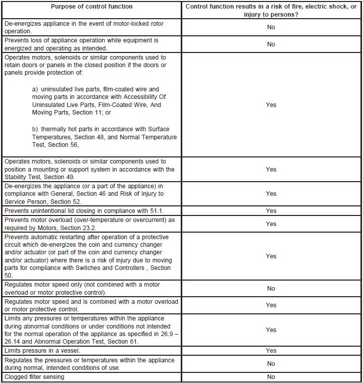
| APPENDIX A | New table added; Operating and protective (²safety critical²) control functions (Normative)
|
CUSTOMERS PLEASE NOTE: This Table and column "Verdict" can be used in determining how your current or future production is or will be in compliance with new/revised requirements.