SUN - UL 1449 Rev 09162013, Surge Protective Devices
Effective March 11, 2016
Effective Date (see Schedule below): March 11, 2016
Impact Statement: A review of all Listing Reports is necessary to determine which products comply with new/revised requirements and which products will require re-evaluation. NOTE: Effective immediately, this revised standard will be exclusively used for evaluation of new products unless the Applicant requests in writing that current requirements be used along with their understanding that their listings will be withdrawn on Effective Date noted above, unless the product is found to comply with new/revised requirements.
Overview of Changes: UL 1449 3rd edition was revised to incorporate new/revised requirements pertaining to all SPD types, supplementary protection, testing, test equipment, ratings, and markings. Specific details of new/revised requirements are found in table below.
Client Action Required:
Information - To assist our Engineer with review of your Listing Reports, please submit technical information in response to the new/revised paragraphs noted in the attached or explain why these new/revised requirements do not apply to your product (s).
Current Listings Not Active? – Please immediately identify any current Listing Reports or products that are no longer active and should be removed from our records. We will do this at no charge as long as Intertek is notified in writing prior to the review of your reports.
| Clause | Verdict | Comment |
|---|---|---|
| 7 | Info | Enclosure |
| 7.1 | Info | Type 1 and Type 2 SPDs |
| 7.1.4 | Additions to existing requirements are underlined The enclosure shall comply with the applicable mechanical/electrical property considerations, flammability, moisture-absorptive properties and thermal requirements for fixed and stationary equipment as specified in the Standard for Polymeric Materials – Use in Electrical Equipment Evaluations, UL 746C. Exception No. 1: The enclosure of a Receptacle SPD shall comply with the enclosure requirements in the Standard for Attachment Plugs and Receptacles, UL 498. Exception No. 2: The enclosure of a Circuit Breaker SPD shall comply with the enclosure requirements in the Standard for Molded Case Circuit Breakers, UL 489. Exception No. 3: The enclosure of a one-piece Molded Case SPD shall comply with the enclosure requirements in the Standard for Molded Case Circuit Breakers, UL 489. Exception No. 4: The enclosure of a Pullout SPD shall comply with the enclosure requirements in paragraph 31A.2. | |
| 12 | Info | Supplementary Protection |
| 12.2 | Additions to existing requirements are underlined and deletions are shown
Exception No. 1: A fuse that is capable of clearing a fault current of not less than that indicated in Table 12.1 and complies with the requirements in the Standard for Low-Voltage Fuses – Part 14: Supplemental Fuses, UL 248-14, is able to be used as a supplementary protection device. Exception No. 2: A circuit breaker or fuse that complies with 12.5 is able to be used as a supplementary protector. | |
| 25 | Info | Capacitors |
| 25.4 | New clause added; A discharge means, such as a bleeder resistor, shall be provided to drain the charge stored in a capacitor if necessary to comply with the requirements in Capacitance, Section 59A | |
| 31A | New section added; Molded Case Surge Protective Devices | |
| 31A.1 | Molded Case SPDs shall additionally comply with the requirements in the Standard for Molded-Case Circuit Breakers, Molded-Case Switches, and Circuit Breaker Enclosures, UL 489. The investigation will include, but is not limited to: a) Spacings evaluation, such as electrical spacings, wiring space, and wire bending space. b) Openings in enclosures or the deadfront when the classified SPD is placed in a specified panelboard and is used with filler plates or other circuit breakers. c) Accessibility of wiring terminals with the classified SPD installed in a specified panelboard. d) Other construction requirements in this standard. e) Connectability features that are equivalent to a specified circuit breaker, including wiring terminal temperature rating, and field wiring conductor temperature rating and type. | |
| 36 | Info | Temperature Test |
| 36.15 | New clause added; Molded Case SPDs, subjected to the Temperature Test, shall additionally comply with the Temperature Test requirements Section 7.1.4 of UL 489. | |
| 37 | Info | Surge Testing |
| 37.1.1 | Additions to existing requirements are underlined and deletions are shown These tests are conducted to verify that SPDs are able to operate in surge environments and comply with the criteria outlined in 37.8.3. Different tests are conducted for the different SPD Types: a) 1) The sample undergoing the Nominal Discharge Current Test is first subjected to a 6 kV/3 kA Combination Wave Surge Test to establish the benchmark measured limiting voltage. From this benchmark measured limiting voltage the voltage protection rating (VPR) is also determined in accordance with Section 63.2. 2) The VPR is based on the measured limiting voltages recorded after the first set of 6 kV/3 kA Combination Wave Surge Tests. The measured limiting voltages are averaged per mode. The per mode average is the VPR and is verified after the second set of 6 kV/3 kA Combination Wave Surge Tests. b) Type 3 and Type 4 SPDs (intended for locations in which a Type 3 SPD may be installed), are subjected to the Operating Duty Cycle Test. 1) The sample undergoing the Operating Duty Cycle test is first subjected to a 6 kV/3 kA Combination Wave Surge Test to establish a voltage protection rating (VPR). 2) The measured limiting voltage is recorded for the 6 kV/3 kA Combination Wave Surge Tests before and after the Operating Duty Cycle Test and the Voltage Protection Rating is determined and verified as described above. | |
| 37.2 | Info | Test equipment |
| 37.2.3 | Info | Oscilloscope |
| 37.2.3.1 | Additions to existing requirements are underlined and deletions are shown | |
| 37.2.6 | New section added; Determination of no signal noise during determination of voltage protection rating | |
| 37.2.6.1 | The noise associated with each surge test setup shall be measured and recorded. The noise shall be subtracted from the actual measurement when determining the resultant amplitude associated with a test. | |
| 37.2.6.2 | Connect the SPD to the surge generator in accordance with 37.5 and 37.6. Connect the voltage probes in accordance with 37.2.4. | |
| 37.2.6.3 | Set the oscilloscope in accordance with 37.2.3 using the appropriate voltage scale settings (volts/division) for the expected result. If the voltage scale settings are modified during the test, repeat this procedure using the new voltage scale setting. | |
| 37.2.6.4 | Without applying a surge, trigger the oscilloscope and record the voltage (math) maximum. This is the no signal noise. Repeat five times recording the amplitude each time. | |
| 37.2.6.5 | Average the five no signal noise measurements to compute the average no signal noise for the determination of the voltage protection rating. | |
| 37.2.6.6 | This value is to be derived for and subtracted from the measured limiting voltage during the determination of the voltage protection rating (see 37.6). | |
| 37.2.7 | New section added; Determination of no signal noise for current | |
| 37.2.7.1 | The noise associated with each surge test setup shall be measured and recorded. The noise shall be subtracted from the actual measurement when determining the resultant amplitude associated with a test. | |
| 37.2.7.2 | With the current monitor described in 37.2.5 in place, connect a suitable short circuit between the connection points at the output of the surge generator normally used to connect the SPD to the generator. An example of a suitable short circuit would be a 6 AWG wire of minimal length. | |
| 37.2.7.3 | Set the oscilloscope in accordance with 37.2.3 using the appropriate voltage scale settings (volts/division) for the expected result. If the voltage scale settings are modified during the test, repeat this procedure using the new voltage scale setting. | |
| 37.2.7.4 | Without applying a surge, trigger the oscilloscope and record the voltage (math) maximum. This is the no signal noise. Repeat five times recording the amplitude each time. | |
| 37.2.7.5 | Average the five no signal noise measurements to compute the average no signal noise for current. | |
| 37.2.7.6 | This value is to be derived for and subtracted from the current measured during the calibration of the surge generator for the determination of the voltage protection rating and the nominal discharge current test. | |
| 37.3.1.2 | New clause added; Oscilloscopes that are equipped with noise filtering capabilities (commonly referred to as ²high resolution² or ²enhanced resolution²) may be set to produce effective sampling rates and bandwidths (see 37.2.3, 37.2.6, and 37.2.7) to aid in the mitigation of erroneous noise on the displayed waveforms to ensure accuracy when determining the calibration characteristics. This clause applies to all sub-clauses of 37.3. | |
| 37.7.3 | Additions to existing requirements are underlined During the application of these surges the samples are unenergized. Surges shall be applied in three groups of five surges. Within 1 second after the application of each surge, the manufacturer’s specified (declared) MCOV shall be applied for 60 seconds ±5 seconds. A maximum of 1 minute ±15 seconds between surges is permitted. After each group of 5 surges, the sample shall rest for 30 minutes ±5 minutes. After the 15th surge, the MCOV shall be re-applied for at least 15 minutes. Exception No. 1: After each group of 5 surges, the sample may rest for less than 30 minutes if agreeable to all concerned. Exception No. 2: SPDs that permit follow current, such as gas tubes and air gap devices (see 37.2.2.3), shall be tested with the unit energized by applying the surge initially at 0 degrees on the AC voltage waveform and then incrementing the angle by 30 degrees for each of the 15 surges. | |
| 37A | Info | Type 5 SPD Surge Testing |
| 37A.2 | New clause added; Type 5 SPDs with rated operating temperature above 85°C shall comply with 37A.1 with the Aging Test in Section 59D conducted during the 37A.1 sequence following the Vn @1ma DC test in 37A.1 (a). Immediately following completion of the Aging Test, while the samples are still in a heated condition, the samples are to be subjected to the nominal discharge current in 37A.1 (a). | |
| 39.1.2 | Info | The voltages in Table 39.1 shall be applied during the Limited Current Abnormal Overvoltage Test. During the Short Circuit Current Rating Test and the intermediate Current Tests, the voltages in Table 39.1 may be used if exception to 39.2.2 is not applied. |
| 39 | Info | Current Testing |
| Table 39.1 (2013) | Added additional nominal voltage ratings and test voltage. Table 39.1- September 16, 2013 Version: 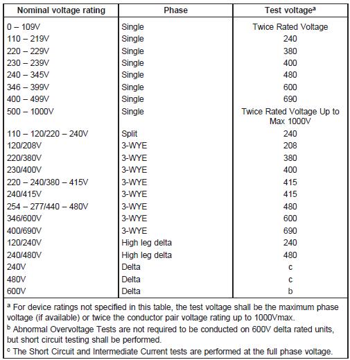 | |
| Table 39.1 (2009) | Info | Table 39.1- June 1, 2009 Version: 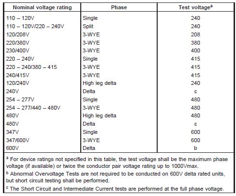 |
| 39.1.12 | Additions to existing requirements are underlined Following the tests described in 39.2, 39.3, and 39.4, the same representative devices are to be subjected to and comply with the tests below according to their Type: a) Type 3 SPDs, except receptacle SPDs, and Type 4 component assemblies intended for Type 3 applications, shall be subjected to the Leakage Current Test requirements in Section 34. The Leakage Current Test shall be conducted within 5 minutes of the end of the Current Tests. b) Types 1, 2, 3 and Type 4 component assemblies shall be subjected to the Grounding Continuity Test requirements in Section 40. c) Molded Case SPDs of the Pullout design shall be subjected to and comply with the Pullout Insertion and Withdrawal Test, Section 59D, only on each of the samples subjected to the tests described in 39.2, 39.3, and 39.4. | |
| 39.1.22 | New clause added; Molded Case SPDs shall be subjected to the tests described in 39.2 (Short Circuit Current Rating Test), 39.3 (Intermediate Current Test), and 39.4 (Limited Current Abnormal Overvoltage Test), and installed in a panelboard as described in the Standard for Panelboards, UL 67, paragraph 23.2.2.2 - 23.2.2.4. Additional circuit breakers specified by the panelboard manufacturer are to be used to surround the Molded Case SPD under test as required by UL 67, paragraph 23.2.2.2. Exception: Testing may be conducted without installing the Molded Case SPD in a panelboard, provided the test is conducted with the Molded Case SPD wrapped with a double layer of cheesecloth and determining that none of the conditions detailed in paragraph 39.1.11 result. | |
| 39.1.23 | New clause added; Molded Case SPDs, intended for use in other manufacturer’s panelboards, shall be subjected to the tests described in 39.2, (Short Circuit Current Rating Test), 39.3 (Intermediate Current Test), and 39.4 (Limited Current Abnormal Overvoltage Test), with the Molded Case SPD installed in a panelboard as described in the Standard for Panelboards, UL 67, paragraph 23.2.2.2–23.2.2.4. Additional circuit breakers specified by the panelboard manufacturer, as well as those that may be specified by other manufacturers, are to be used to surround the Molded Case SPD under test as required by UL 67, paragraph 23.2.2.2. Exception: Testing may be conducted without installing the Molded Case SPD in a panelboard, provided the test is conducted with the Molded Case SPD wrapped with a double layer of cheesecloth and determining that none of the conditions detailed in paragraph 39.1.11 result. | |
| 59D | New section added; Aging Test | |
| 59D.1 | Three samples of Type 5 SPDs shall be placed in a full draft circulating air oven maintained at rated operating temperature and connected to source of supply at rated MCOV for 1000 hours. | |
| 59E | New section added; Pullout Insertion and Withdrawal Test | |
| 59E.1 | The plug-in connection members on a pullout module and on the pullout base, and the plug-in connection members on a Pullout SPD and on the receiving member of the panelboard, shall have the strength necessary for the forces applied during insertion and withdrawal of the Pullout SPD pullout module without causing any bus distortion, damage to the plating, or other damage to panelboard or Pullout SPD. | |
| 59E.2 | To determine compliance, five samples of the Pullout Module and one sample of the Pullout Base shall be tested. With the Pullout Base mounted in the panelboard in the intended manner, each of the five Pullout Modules shall be inserted and withdrawn one time each from the Pullout Base. | |
| 59F | New section added; Capacitor Failure Test | |
| 59F.1 | If required by the Exception of 25.3, capacitors employed in Type 1 SPDs shall be permanently mechanically (driving a nail through the capacitor where the nail should not short out the capacitor to ground nor reduce spacings to other electrical paths) or electrically (as specified in 10.2.2 of UL 810) failed and three samples tested at the short circuit current rating of the SPD in accordance with the Short Circuit Current Rating Test procedure covered by Clauses 39.2.1 to 39.2.4. Permanent failure of a capacitor is demonstrated by the flow of short circuit current until interrupted by an overcurrent protection device or for 3 full cycles. | |
| 59F.2 | Capacitors rated 1 uF or less may be failed in accordance with 59F.1, or may be replaced with jumper wire having a minimum gauge size equal to the capacitor leads. The jumper wire shall not open during testing. | |
| 63 | Info | General (RATINGS) |
| 63.1 | Additions to existing requirements are underlined An SPD, including Type 1, 2, 3 Component Assemblies, shall be provided with the following ratings: the operating voltage rating (volts), ac power frequency (Hz), and voltage protection ratings (volts or kilovolts) as described in 63.2. For a two-port SPD, the ratings shall include the load current rating (amperes). Type 1 and 2 SPDs shall also be provided with In and MCOV ratings. Type 1 SPDs, Type 2 SPDs and Permanently-Connected Type 3 (other than receptacle type) SPDs intended to be installed at the utilization equipment being protected, shall also be provided with a Short Circuit Current Rating (SCCR). | |
| 64 | Info | Details (MARKINGS) |
| 64.11 | Additions to existing requirements are underlined Type 1 SPDs or Type 2 SPDs and Permanently-Connected Type 3 (other than receptacle type) SPDs intended to be installed at the utilization equipment being protected, shall be marked ²Suitable For Use on a Circuit Capable of Delivering Not More Than __a__ rms symmetrical Amperes². a) The available fault current ²a² shall be one of the values indicated in Table 64.2 but not less than given in Table 64.3. Exception No. 1: The marking may be on a separate sheet or in the installation instruction if there is not sufficient room on the device for the marking. If this exception is employed, then ²SCCR =xxxx kA² is required to be marked on the product. | |
| 64.12 | Additions to existing requirements are underlined and deletions are shown
a) Class CC, CD, G, H, J, L, R, T or K fuse. Reference to Class H or Class K fuses shall not appear in the marking if the indicated rms symmetrical fault current is greater than 10,000 A. b) Current rating of fuse or circuit breaker. c) Nominal system voltage. | |
| 64.27 | New clause added; Molded Case SPDs shall additionally be marked with the applicable Termination markings, as required by Section 9.1.2, UL 489. | |
| 64.28 | New clause added; A Pullout SPD ²Pullout Module² shall additionally be marked: a) To indicate the Cat. Nos. of the pullout base(s) with which it can be used. b) De-energize panelboard before replacing SPD pullout Module into panelboard, or equivalent, visible after installation. | |
| 64.29 | New clause added; A Pullout SPD Pullout Base shall additionally be marked: a) With the Manufacturers name and Cat. No.on the front of the pullout base in a location that is visible after installation. b) With the Cat. No..of the pullout module(s) that can be used with this pullout base. |
CUSTOMERS PLEASE NOTE: This Table and column "Verdict" can be used in determining how your current or future production is or will be in compliance with new/revised requirements.