CSA E60974-1, Arc welding equipment — Part 1: Welding power sources
Effective November 30, 2018
Effective Date: November 30, 2018
Impact Statement: A review of all Listing Reports is necessary to determine which products comply with new/revised requirements and which products will require re-evaluation. NOTE: Effective immediately, this revised standard will be exclusively used for evaluation of new products unless the Applicant requests in writing that current requirements be used along with their understanding that their listings will be withdrawn on Effective Date noted above, unless the product is found to comply with new/revised requirements.
Overview of Changes: New and revised requirements for Testing, Construction, Instructions and Markings. Specific details of new/revised requirements are found in table below.
If the applicable requirements noted in the table are not described in your report(s), these requirements will need to be confirmed as met and added to your report(s) such as markings, instructions, test results, etc. (as required).
Client Action Required:
Information – To assist our Engineer with review of your Listing Reports, please submit technical information in response to the new/revised paragraphs noted in the attached or explain why these new/revised requirements do not apply to your product (s).
Current Listings Not Active? – Please immediately identify any current Listing Reports or products that are no longer active and should be removed from our records. We will do this at no charge as long as Intertek is notified in writing prior to the review of your reports.
| Clause | Verdict | Comment |
|---|---|---|
| 5 | Info | Tests |
| 5.1 | [Replace this clause with the following] The tests shall be carried out on new, dry, and completely assembled welding power sources at an ambient air temperature between 10 °C and 40 °C. When placing the measuring devices, the only access permitted shall be through openings with cover plates, inspection doors, or easily removable panels provided by the manufacturer. The ventilation in the test area and the measuring devices used shall not interfere with the normal ventilation of the welding power source or cause abnormal transfer of heat to or from it. Liquid-cooled welding power sources shall be tested with liquid conditions as specified by the manufacturer. Unless otherwise specified, the equipment shall be supplied by a rated supply voltage with a tolerance of ±5%. | |
| 5.4 | Type Tests | |
| [Replace Item a) with the following] a) visual inspection, see 3.7; [Replace Item i) with the following] i) visual inspection, see 3.7. | ||
| 6 | Info | Protection against electric shock |
| 6.1.2 | Clearances [Replace the fourth paragraph with the following] For supply circuit terminals, see E.4A. | |
| 6.1.3 | Creepage distances [Replace the sixth paragraph with the following] For supply circuit terminals, see E.4A. | |
| 6.2.1 | Protection provided by the enclosure [Add the following paragraph] Enclosures for welding power sources specifically designed for outdoor use shall comply with the weather-proof requirements in the water tests of CSA C22.2 No. 100, tested with the power source not running. | |
| 6.3.2 | Isolation between windings of the supply circuit and the welding
circuit [Replace the second paragraph with the following] Between the windings of the supply circuit and the welding circuit, there shall be insulation that conforms to the values given in Table 5. Alternatively, other means specified in CAN/CSA-E61558-1 may be used provided that the complete test requirements of CAN/CSA-E61558-1 are satisfied. | |
| 6.3.4 | Additional requirements for plasma cutting systems [Replace Item b) with the following] b) for manual systems, using torch components recommended by the manufacturer, when an arc current is present: the sides of the plasma tip cannot be contacted by Test Probe 11 of IEC 61032 when it is placed on a flat surface with its centre line perpendicular to it; or the dc voltage between the plasma tip and the workpiece and/or earth is not higher than the values given in 11.1.1. [Replace the note with the following] NOTE:A fault is an abnormal condition resulting from the electrode being in contact with the plasma tip because of missing insulators, sticking of the plasma tip to the electrode, conductive material between plasma tip and electrode, wrong parts, loose parts, electrode abrasion, parts inserted incorrectly, excessive load, or incorrect gas flow. | |
| 7 | Info | Thermal requirements |
| 7.3.1 | Windings, commutators and slip-rings [Replace the third paragraph with the following] Furthermore, for tests at other than 100% duty cycle, the temperature occurring during any full cycle shall not exceed the maximum temperatures given in Table 6. If the heating test is carried out at a temperature other than 40 °C, the maximum temperature measured during the heating test in accordance with 7.1 shall be corrected by adding the difference between 40 °C and the ambient air temperature (see 7.2.5). | |
| 10 | Info | Connection to the supply network |
| 10.3 | Means of connection to the supply circuit [Add the following paragraphs] Welding power sources intended for either permanent or non-permanent connection to the mains shall have provision for connection to the wiring system in accordance with the Canadian Electrical Code, Part I. Section 42-004 of the Canadian Electrical Code, Part I contains additional requirements for non-permanently connected (cordconnected) welding power sources. The terminal parts and all other components intended for connection to the power supply system shall comply with CAN/CSA-C22.2 No. 0. | |
| 10.9 | Supply cables [Add the following paragraphs] Flexible cord used for connection to the power supply system shall comply with the requirements of CSA C22.2 No. 49. All welding power sources provided with a cord shall have an extra-hard-usage-type cord or extra-hard-usage-type power supply cable, as specified in Table 11 of the Canadian Electrical Code, Part I. | |
| 10.10 | Supply coupling device (attachment plug) [Add the following paragraphs] Attachment plugs intended for connection of welding power sources to the power supply system shall comply with a) CSA C22.2 No. 21 for moulded-on-type attachment plugs; or b) CSA C22.2 No. 42 for disassembly-type attachment plugs. The rating of the attachment plug shall conform to Rule 42-004 of the Canadian Electrical Code, Part I. | |
| 11 | Info | Output |
| 11.2.8 | Additional requirements [Delete this clause] | |
| 14 | Info | Mechanical provisions |
| 14.1 | General requirements [Add the following paragraph and note] Provided that the welding power source is marked as specified in 17.2, no covering shall be required across the bottom of a floor-mounted enclosure if the lower edge of the enclosure is within 150 mm of the floor and if live parts of the device are situated 150 mm or more above the lower edge of the enclosure. NOTE 1A:This requirement does not apply to the prime mover of engine-driven sets. | |
| 14.2.1 | Enclosure materials [Replace first paragraph with the following] Non-metallic materials intended to protect from contact with live parts, except welding and SELV circuits, shall have a flammability classification of V-0 or better in accordance with IEC 60695-11-10. | |
| 17 | Info | Instructions and markings |
| 17.1 | Instructions [Add the following note after Item f)] NOTE 1A:See Annex H for information on the plotting of static characteristics. [Replace Item h) with the following] h) basic guidelines regarding protection against personal hazards for operators and persons in the work area (e.g., electric shock, fumes, gases, arc rays, hot metal, sparks, and noise); specific reference to CAN/CSA-W117.2 shall be made in the latest revision to the instruction manual; [Delete Item r)] [Add Item sA) as follows] sA) an explanation of the relationship between U0 and OCV (open circuit voltage) using the following words or their equivalent: In some countries, U0 is also known as OCV (see CAN/CSA-W117.2). | |
| 17.2 | Markings [Add the following before the “conformity” paragraph] When required by 14.1, the welding power source shall be marked with the following or equivalent wording: CAUTION: DO NOT MOUNT OVER COMBUSTIBLE SURFACES. For engine-driven power sources with general-purpose ac output receptacles, the status of the neutral conductor shall be marked as follows: NEUTRAL FLOATING or NEUTRAL BONDED TO FRAME (as applicable). Engine-driven power sources with general-purpose dc output receptacles shall be marked with the following: SYSTEM FLOATING or SYSTEM BONDED TO FRAME (as applicable). | |
| Annex E (Normative) | Construction of supply circuit terminals [Add the following clause and table] E.4A Spacings between supply circuit terminals Terminals shall be designed as follows. The spacing between the supply terminals shall be not less than the specified values in Table E.1A. Barriers or means for retaining all the conductor strands (for example, pressure type connectors) shall prevent strands of conductors or lugs from contacting other strands of conductors or other lugs connected to adjacent terminals and shall maintain the spacing provided. Table E.1A — Spacing between supply circuit terminals 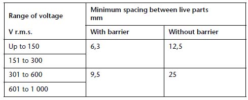 Conformity shall be checked by measurement of the spacings as in IEC 60664-1. |
CUSTOMERS PLEASE NOTE: This Table and column "Verdict" can be used in determining how your current or future production is or will be in compliance with new/revised requirements.